 |
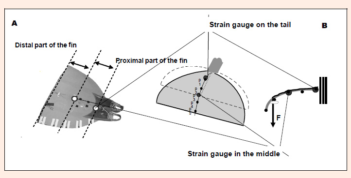
Figure 1.
The monofin used in the research with the strain gauges marked, dividing the monofin into front and end parts (A). Illustration of the monofin scaling concept consisting of simulating balanced load on its surface at each point where flexing force was applied (B).