 |
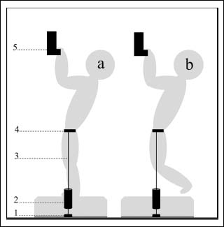
Figure 2.
Schematic presentation of the test set-up during the isometric pull-up showing 1) expansion bolt in the concrete floor, 2) the force cell, 3) the static daisy chain, 4) the climbing harness, and 5) the 23 mm rung. The gray figure represents the climber before (a) and while (b) exerting maximal force. No horizontal or vertical displacement occurs between the two images.