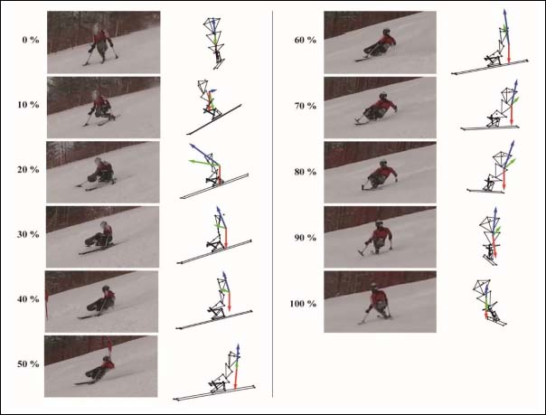
Figure 2. Typical example of one turn. The images were obtained from a video camera and stick pictures during a right turn by the LW11 skier is also shown. View angles of the stick pictures were manually adjusted to correspond to the plane of the video images. The vectors pointing upward (blue) and downward (red) respectively represent the acceleration caused by the resultant force of three external forces (ground reaction forces through a ski and two outriggers and air resistance) and the gravity acceleration. The vector pointing toward the center (green) is the sum of the vectors (blue and red vectors). Both 0% and 100% of time indicate the switching instant of the turns. In the turn shown in the figure, the lateral flexion at the chest joint was approximately maximum at the 80%. At that time point, the angles of flexion, lateral flexion, and rotation toward the outside of the turn at the chest joint were 8, 21, and 3 degrees, respectively. The angle of extension at the hip joint was 3 degrees.