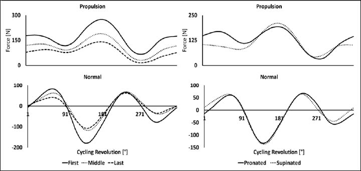
Figure 6. Normal and propulsion crank-pedal forces during an upper-body Wingate. The first column on the left represents the normal and propulsion force changes during the first, middle, and last revolutions of an upper-body Wingate test. The second column to the right, exhibit the normal and propulsion force changes in the supinated and pronated forearm position during an upper-body Wingate test.